The Industry Leader of Precision
Cold Rolled & Cold Drawn Metal Profiles
ISO 9001 Certified
UEI: HVHDQ2UJQXJ7 | CAGE: 13A10
Home » What We Do » Profile Capabilities
The Industry Leader of Precision
Cold Rolled & Cold Drawn Metal Profiles
ISO 9001 Certified
UEI: HVHDQ2UJQXJ7 | CAGE: 13A10
Home » What We Do » Profile Capabilities
| Characteristic | Standard Rolling Tolerance | Standard Drawing Tolerance | Optional |
|---|---|---|---|
| Linear | ± .002″ Thickness ± .005″ Width | ±.002″ All | ±.0005″ |
| Radial | ±.010″ Shape Dependent | ± .005″ small radii ± .010″ large radii | ± .002″ |
| Corners/Fillets | Dependent on location on profile | .015″ max-90° Blend on Obtuse | .005″ max – 90° Obtuse – Review |
| Surface Finish | 63 Ra | 125 Ra | 40 Ra |
| Size Limitations | Typically less than 1.5″ | Typically Range .032** to 2.0″ | Configuration Dependent |
| Characteristic | Standard Tolerances | Optional |
|---|---|---|
| Lengths | 10′-12′ from coil raw material 8′-14′ from bar raw material with variation in length to be within ± 1.0″ | Dead Lengths Abrasive / Cold Saw Pieces ± .005″ on cut pieces |
| Mechanical Properties | Rockwell Hardness reported if required by customer | Outside Testing Available |
| Surface Coatings | Carbon & Alloy – Phosphate & Soap Stainless – Cleaned dull matte finish Copper & Brass – Residual Soap | Bright & Shiny Appearance |
| Cut Ends | Deformed Pinch cut/ Shear cut | Shaped Shear, Saw cut ends |
| Shipping Containers | Reddi Crate™ | Wooden Boxes, Spools Banded Bundles |
| Hardness Range Values | Carbon HRB 75- HRB 95 Alloy HRB 90 – HRC 28 Stainless HRB 90-HRC 25 Copper & Brass HRB 60-HRB 85 | May be adjusted by modification of cold work reductions |
| Temper | As Drawn or As Rolled | Stress Relieved Annealed Heat Treated (Outside) |
| Straightness Twist | .020″ / Ft. cumulative .030″ / Ft. cumulative – small wire ± 2° per foot | .005″ / Fl |
| Decarburization | Not checked unless there is a customer requirement | .005″ max total and or partial- Requires surface improved raw stock |
| CATEGORY | GRADE |
|---|---|
| Carbon Steel | 1006, 1010, 1018, 1022, 1030, 1040, 1050, 1060, 1070, 1095 |
| Free Cutting | 1117, 1137, 1441. 1144, 1215, 12L14 |
| Alloy Steels | 4130, 4140, 4150, 4340, 4820, 6150, 8620, 8640, 8650, 9310, 52100 |
| 300 Series Stainless | 302, 303, 304, 305, 316, 316LS, 321 |
| 400 Series Stainless | 403, 405, 410, 416, 420, 430, 430F, 430FR, 450, 455, Trimrite |
| High Temperature | Pyromet A286, 600, 625, 718 |
| Copper, Brass, Bronze | 101, 102, 110, 182, 187, 230, 260, 270, 335, 340, 360, 464, 510, 521, 544, 651, 655, 706, 715, 752 |
| Nickel- Copper | 400, 405 |

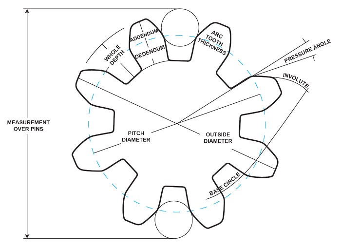
Gear is not checked to any specific AGMA level as tooth profile is checked using an optical comparator.